Video lecture for this chapter
This material (including images) is copyrighted!.
See my copyright notice for fair use
practices.
Radio astronomy has its roots back in the 1930's when Karl Jansky
accidentally
detected radio emission from the center of the Milky Way as part of his
research
on the interference on transatlantic phone lines. The British advanced
radio
antenna technology in their
development of radar technology to fight the German warplanes in World War
II.
After the war, astronomers adapted the technology to detect radio waves
coming
from space.
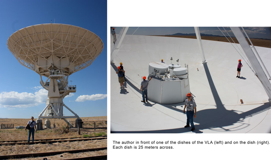
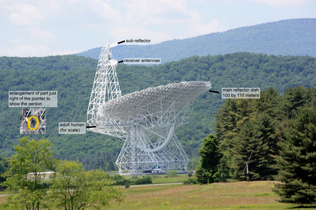
The two images above show the author with one of the dishes of the Very Large Array described more fully in the Resolving Power section.
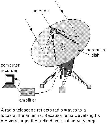
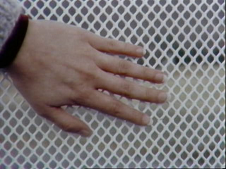 A radio telescope uses a large metal dish or wire mesh, usually
parabolic-shaped,
to reflect the radio waves to an antenna above the dish. An example of a
mesh is shown at
left. This was the mesh of the parabolic dish for the former 100-meter
radio telescope at
Green Bank, West Virginia (photo courtesy of
National Radio
Astronomy Observatory). Looking
from
underneath a radio
telescope, a person can see the clouds in the sky overhead but to
the much longer
wavelength radio waves, the metal mesh is an excellent reflector. See also images
from the Parkes Radio Telescope. Radio telescopes designed to also receive smaller wavelengths, such as the GBT pictured above, have solid metal dishes. The GBT's metal surface is made up of 2004 panels, each roughly the size of a queen-sized bed, mounted on actuators to fine-tune the shape as the telescope is tilted and wind speed and direction changes.
The signal from the antenna is sent
to an amplifier to magnify the very faint signals. At the last step, the
amplified signal
is processed by a computer to turn the radio signals into an image that
follows the
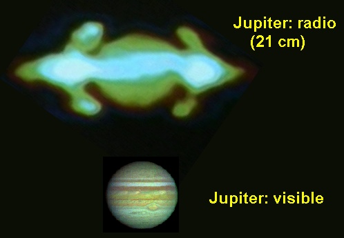
shape of the radio emission. False colors are used to indicate the
intensity of
the radio emission at different locations. An example is shown below for
Jupiter. Charged
particles in its magnetic field produce a large amount of radio energy in
donut-shaped
regions around its center. A visible band image of Jupiter is shown below
the radio image.
Radio telescopes are much larger than optical telescopes because radio
wavelengths
are much longer than optical wavelengths. The longer wavelengths means
that the
radio waves have lower energy than optical light waves. In order to collect
enough radio photons to detect a signal, the radio dishes must be very
large.
Both optical and radio telescope reflectors use a parabolic shape to
perfectly
focus the light to a point. Increasing the size of the radio dish is also
necessary
in order to improve the clarity of the radio images. I will discuss the
issue of
image clarity further in the next two sections.
Radio telescopes detect the emission from cool clouds of hydrogen in the
space
between the stars. Hydrogen atoms are the most common type of atoms in the
universe
and much of the hydrogen gas is too far away from any star to produce
emission in
the optical wavelength band. In addition, there are cold clouds made of over a hundred different types of molecules including organic molecules. Stars and planetary systems form in these molecular clouds. Therefore, radio telescopes are a vital tool
in
understanding the universe. I will discuss further the use of radio waves
to
explore the material between the stars and the structure of our galaxy in
the
interstellar medium chapter.
 Go back to previous section --
 Go to next section
last updated:
January 19, 2022
Is this page a copy of Strobel's
Astronomy Notes?
Author of original content:
Nick Strobel

 A radio telescope uses a large metal dish or wire mesh, usually
parabolic-shaped,
to reflect the radio waves to an antenna above the dish. An example of a
mesh is shown at
left. This was the mesh of the parabolic dish for the former 100-meter
radio telescope at
Green Bank, West Virginia (photo courtesy of
